
Pinbot Flipper, Switch & Board Repair
- Symptom
- A 1986 Williams Pinbot with a left flipper at about a quarter strength and Switch 28 and 29 reported at every startup. Opening the backbox also found years of alkaline battery corrosion on the CPU board.
- Diagnosis
- The original flipper coil had failed. Its replacement was then destroyed by an end-of-stroke switch we wired wrong, which left the coil running in a state it's only designed to be in for a fraction of a second. The switch errors were two broken solder joints, one on each target's own row wire, with the shared Column 4 wiring intact. The board damage was battery leakage spreading from the holder into the traces and an IC.
- Fix
- EOS wiring corrected against the factory schematic and a third coil fitted at our cost, not the customer's; both flippers now pull and hold, which is itself the proof the wiring is right. Both row wires re-soldered. Board corrosion neutralized, damaged traces repaired, the on-board battery holder replaced with an off-board one, and the corroded chip replaced on a new socket.
A 1986 Williams Pinbot came in with three separate problems: a left flipper at about a quarter of its normal strength, Switch 28 and Switch 29 reported at every startup, and a CPU board that had been quietly dissolving under its own batteries for years. Three faults, in three different parts of the machine.
What This Page Is For
The flipper circuit on a System 11 machine sets a trap, and this job walked into it. The end-of-stroke switch on these isn't wired in line with the coil the way you'd expect, it's wired across one of the windings, and getting that connection wrong doesn't produce an error or a dead machine. It produces a flipper that plays normally for about ten minutes and then a coil you can't hold onto.
That's what happened here, on our own wiring. It's on this page because the trap is worth understanding, and because it will catch anyone working on one of these machines.

Fault One
The Flipper, and Three Coils
Jump to the switch errors or the corroded board if the meter readings aren't what you're here for.
The Symptom, and the First Coil
The left flipper had roughly a quarter of its normal strength. Enough to move the ball, nowhere near enough to play. That coil had genuinely failed, so it came out and a replacement went in: the part the manual specifies, an FL-23-600/30-2600 rated for 50 VDC.
The game ran for about ten minutes. Then both flippers stopped, the left coil was very hot, and there was a slight electrical smell. Nothing under the playfield looked burned.
The machine went off at that point and stayed off, rather than getting run again to see whether it would do it twice. That's not caution for its own sake. A coil running away takes its connector, its harness and often the driver transistor with it, and the distance between "replace a coil" and "repair a board" is about sixty seconds of deciding not to press on. The heat was the useful information, and it had already arrived.
How a System 11 Flipper Is Supposed to Behave
Pinbot is a 1986 Williams game on the original System 11 platform, using a series-wound flipper arrangement. The coil has three lugs because there are two windings on one core doing completely different jobs:
- The power winding is heavy wire and few turns, so it is very low resistance. It exists to move the plunger, hard, for a fraction of a second.
- The hold winding is fine wire and many turns, so it is high resistance. It exists to keep the flipper up once it's already there, on a small fraction of the current.
The end-of-stroke switch decides which is in play, and the detail that matters is how it's wired: in parallel, across the hold winding.
- At rest, the EOS switch is closed. It shorts the hold winding out of the circuit entirely, so the flipper sees only the low resistance of the power winding. That's what lets it pull hard.
- At the end of travel, the EOS switch opens. The hold winding drops back in, in series. Total resistance jumps by a factor of thirty, current falls with it, and the flipper can sit up against a ball without cooking.
Two failure modes fall out of that, and they're opposites. If the hold winding never gets shorted out, the flipper is weak, because it's trying to do the stroke on hold current. If it never gets un-shorted, the coil burns, because it's holding at stroke current. Either way the changeover doesn't happen, the coil ends up living in a state it was only ever designed to be in for a moment, and the part that pays for it is the coil rather than whatever put it there.
The Wiring Trap That Cooked the Second Coil
The second coil burned out because I wired the end-of-stroke switch wrong. As far as I can tell it was a perfectly good coil when it went in. It's worth walking through the trap, because it's a well-set one and it will catch anyone working on one of these.
Almost every switch in a pinball machine is in line with the thing it controls. Open the switch, the thing stops. The EOS switch on a series-wound flipper isn't like that. It sits across the hold winding, and its job is a changeover rather than an on/off: it decides which winding the circuit sees, not whether the circuit is live. Wire it to the wrong lug and you don't break the flipper. The flipper still fires. What you break is the handover between the two windings, so the coil never leaves the state it's only supposed to occupy for a fraction of a second.
That's why it takes ten minutes rather than announcing itself. A flipper on a botched EOS connection doesn't throw an error, doesn't blow a fuse on the first shot and doesn't behave obviously wrongly at the button. It plays. Meanwhile the coil is dissipating continuously at a level it was designed to take in bursts, and the only sign is heat, which lives under the playfield where nobody is looking. By the time the symptom is visible, the damage is done.
The currents recorded further down are consistent with that: during what should have been the power stroke, this coil was carrying roughly what it should only be carrying while holding. Those readings didn't diagnose it, the hot coil did. But they line up, and it's worth knowing they line up, because the same arithmetic is what tells you whether a flipper circuit is doing its changeover on any machine with this arrangement.
The customer wasn't charged for that coil.
What a Meter Can and Can't Tell You Here
With power removed, I labeled the three terminals A, B and C left to right for note-taking and measured between each pair:
| Measurement | Reading | What it establishes |
|---|---|---|
| A to B | 2.5 Ω | A low-resistance winding, continuous |
| B to C | 75 Ω | A high-resistance winding, continuous |
| A to C | 75 Ω | The two windings end to end, through the junction at B |
Those readings are arithmetically correct, not just plausible. The part number describes the windings: 23-600 is 600 turns of 23 AWG and 30-2600 is 2600 turns of 30 AWG. Run that through a wire table with a sensible mean turn length and you get roughly 2.5 Ω and roughly 70 Ω. And 2.5 plus 75 is 77.5 against an A-to-C reading of 75, which on a handheld meter is the same number, and which identifies B as the junction lug where the two windings meet.
What that establishes is narrow and genuinely useful: both windings are continuous, the part matches its own label, and — the one that matters most on this job — which physical lug is which, established by measurement rather than by which one happens to sit in the middle. Identifying the junction lug with a meter takes about thirty seconds and it is precisely the step that stops a wiring error before it becomes one.
What it does not establish is that the coil will get what it needs. A resistance reading is taken on a coil sitting cold, still and under no load. It's good at exactly one thing, proving a winding hasn't gone open, and it is blind to a handful of shorted turns among 2600, to a marginal joint that holds up to a meter's milliamps and collapses under a stroke, and to anything that only shows up warm. It also says nothing at all about how the coil is connected — which, on this job, was the whole problem. A clean bench reading is not a working circuit.
Where Voltage Stopped Being Useful
Supply measurements sat near the expected 50 V range depending on meter reference and polarity, so the machine had voltage. Across the low-resistance section, though, the reading was about 3 to 3.5 V initially and then about 1.5 V, and a brief direct test showed roughly 0.5 to 1 A with weak movement.
A voltage reading with no current behind it is one of the easiest ways to be misled by a meter. High resistance almost anywhere, a relay contact, a connector, a crimp, a solder joint, a winding's internal termination, will let a meter display close to full voltage right up until the circuit is asked for real current. So the useful question isn't what the voltage is, it's what the numbers imply together.
Work it from the other end. With the hold winding properly shorted out, the circuit would see 2.5 Ω and the stroke current would be many times what was measured. With the hold winding still in circuit, the path is the full 77.5 Ω, and 50 V across that gives about 0.65 A.
0.65 A sits inside the measured 0.5 to 1 A. And that same current through the 2.5 Ω power winding would drop about 1.6 V across it, against a measured figure of about 1.5 V. Two readings taken for different reasons, landing on the same answer.
What that establishes is narrow but real: during what should have been the power stroke, the coil was being driven at something very close to its hold current, which is the signature of a changeover that isn't happening. On its own it doesn't say whose fault that is — a switch out of adjustment, a broken EOS wire and an EOS landed on the wrong lug all produce it, and only the last of those was written by me. It does, though, give you a number to check a flipper circuit against, and that number is worth having before you put a second coil into a machine that just ate the first one.
The Test That Pointed the Wrong Way
One jumper test connected A to B, and the flipper got weaker. Read quickly, that looks like it points away from the wiring and toward the coil: force a bypass, nothing improves, so the part must be bad. It's the wrong reading, and on this job it was pointing away from exactly where the problem was.
On a series-wound circuit, A to B is the power winding. Jumpering it shorts out the winding that produces the stroke and leaves the 2600-turn hold winding doing all the work alone. Fewer ampere-turns than the series configuration, so a weaker flip isn't evidence of anything, it's the arithmetic of the test. That jumper was never a full-power bypass. On a parallel-wound coil, which is what later Williams generations use, it would have been much closer to one, and that is exactly the sort of assumption that carries across platforms and quietly breaks.
Going back to the factory schematic and re-deriving what the jumper actually did is what kept that from becoming a confident wrong answer, and it's the same schematic that settled the wiring. A test result is only as good as the circuit model behind it, and that goes double when you're reasoning about connections you made yourself and haven't verified.
What Fixed It, and What Proves It
The EOS wiring was corrected against the factory schematic, a third coil went in, and the flippers have pulled and held at full strength since.
That last clause is the verification, not a sign-off. A flipper coil on a miswired EOS doesn't survive normal play; it heats up and fails in minutes, which is precisely what this machine had already demonstrated once. So a coil that goes on working is a direct statement that the changeover is happening and the connection is right.
One thing genuinely isn't known: what was internally wrong with the original coil. It had stopped working and it came out, and once the wiring was right and a good coil was in it there was no reason to section the old one to find out why. That's where the record ends on that particular question, and it stays there rather than getting filled in from memory.
Fault Two
Switches 28 and 29
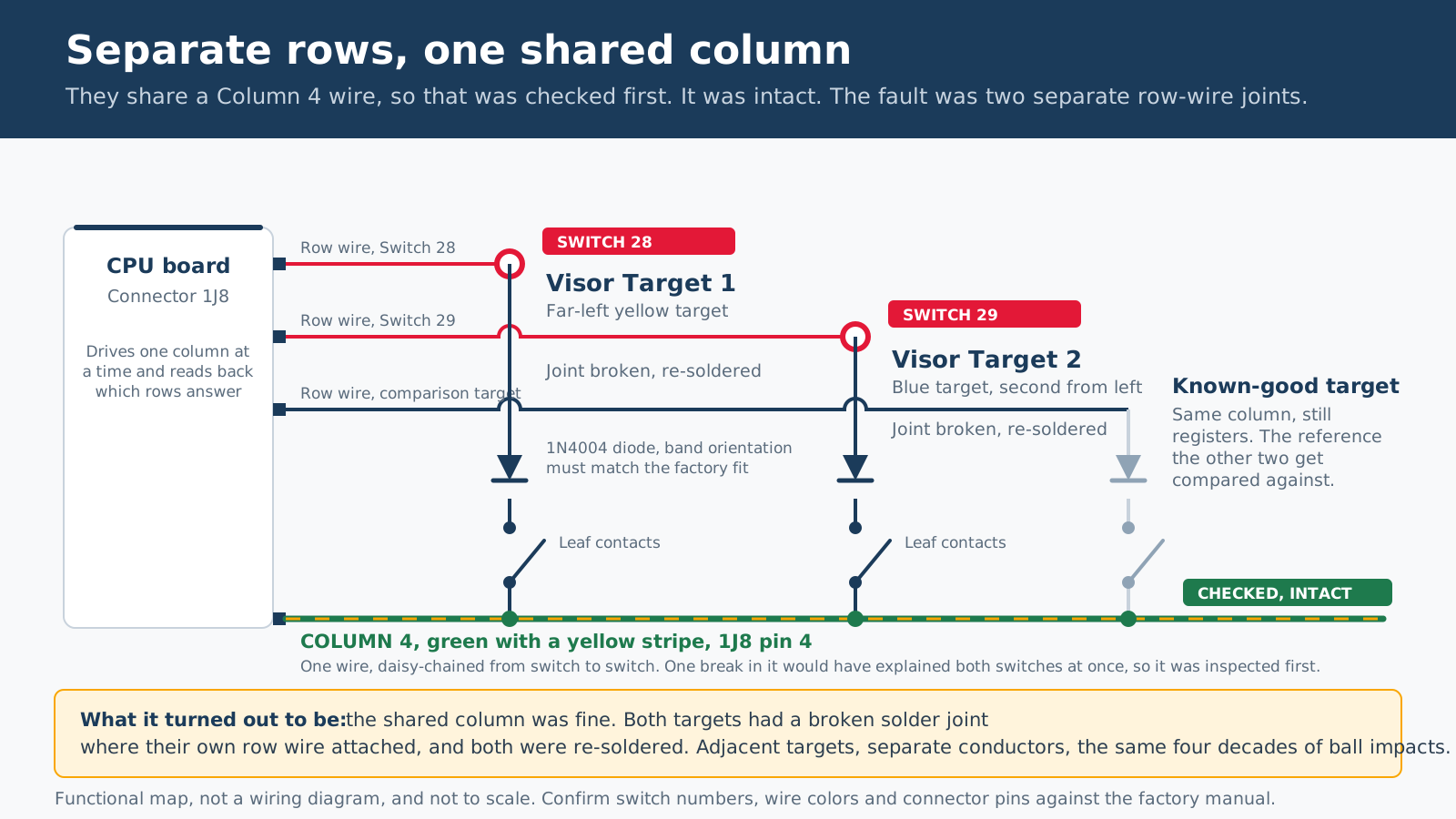
The same machine reported Switch 28 and Switch 29 at startup. Those numbers aren't arbitrary, and the fact that they're consecutive is the most useful thing about them.
What the Machine Was Naming
| Switch | Manual description | Position |
|---|---|---|
| 28 | Visor Target 1 | Far-left yellow visor target |
| 29 | Visor Target 2 | Blue visor target, second from the left |
Both sit in switch-matrix Column 4, carried on the green wire with a yellow stripe at CPU connector 1J8 pin 4. Their row wires are separate, which is how the CPU tells one target from the other. That asymmetry is what decides the order you work the problem in.
What a System 11 Switch Warning Actually Reports
This is the part that sends people to the soldering iron too early. System 11 software tracks whether playfield switches are being used. A switch that hasn't been activated over a run of games, on the order of thirty on this generation, gets reported at power-on.
So the message means "nobody has hit this in a while." That's a prompt to test the circuit, not a declaration that the switch has failed. On an obscure switch that genuinely doesn't get hit, it may mean nothing. On a target sitting in the middle of the playfield that every game should be hitting, it deserves the investigation, and on this machine it earned it.
The realistic candidates behind a real fault are mechanical adjustment, a dirty contact, a broken wire or joint, a failed diode, a connector problem, and much less often a board-level matrix fault. That list is roughly in order of likelihood, and the order it's worked in should match.
Working It, and What It Turned Out to Be
1. Ask the machine, using Switch Edges
- Open the coin door and enter the diagnostic menu.
- Advance to Switch Edges.
- Strike each target with an actual pinball, so the test includes the real mechanical movement rather than a fingertip on the blade.
- Confirm the display reports Switch 28 and Switch 29 separately.
If both register reliably, the electrical path is intact at that moment and the startup report is stale audit history or an intermittent. That's the result that saves the most work, and it's worth two minutes before anything comes apart.
2. Watch the mechanism, not just the switch
With the machine off and the balls out, raise and secure the playfield, then work each target by hand and watch what the switch does: the blade should close the contacts positively rather than brush them, the contacts should be fully open at rest, the target should move freely and return completely, and the switch stack shouldn't be loose or drifting out of alignment. For cleaning gold-plated contacts, a clean business card is the tool. Not sandpaper and not a points file, both of which take the plating off and leave a contact that works beautifully for a month.
3. Check the shared column before anything else
This is where two consecutive switch numbers earn their keep. A break, cracked joint or damaged terminal anywhere in the Column 4 daisy chain interrupts every switch downstream of it, so one shared fault would explain both targets at once, and it's the cheapest thing on the list to inspect. Worth going over: the green-yellow wire at both targets and the adjacent switches in the same column, every solder joint where two wires share a lug, harness movement near the visor mechanism, and connector seating at 1J8.
On this machine the column was intact. That's a useful result too, because it rules out the one explanation that would have covered both symptoms with a single repair.
4. The actual fault
The solder joint where the row wire attached to the switch had broken off. On both targets, independently. Not the shared column, not the diodes, not the contacts, not the board. Two separate mechanical failures of two separate joints. The repair was to re-solder the wires to the switches.
That deserves a sentence on why it isn't the coincidence it first looks like. These two targets sit side by side on the same bank, taking the same repeated ball impacts for close to forty years, with their wiring routed past the same moving visor mechanism. They didn't share a wire, but they shared four decades of the same vibration. A shared cause doesn't have to be a shared conductor, and that distinction is worth holding onto, because the wiring diagram will only ever show you the second kind.
Fault Three
The Battery Damage on the CPU Board
This one wasn't a reported symptom. It was found by opening the backbox and looking, which is the only way this fault ever gets found in time.
Why This Is the Fault That Kills These Machines
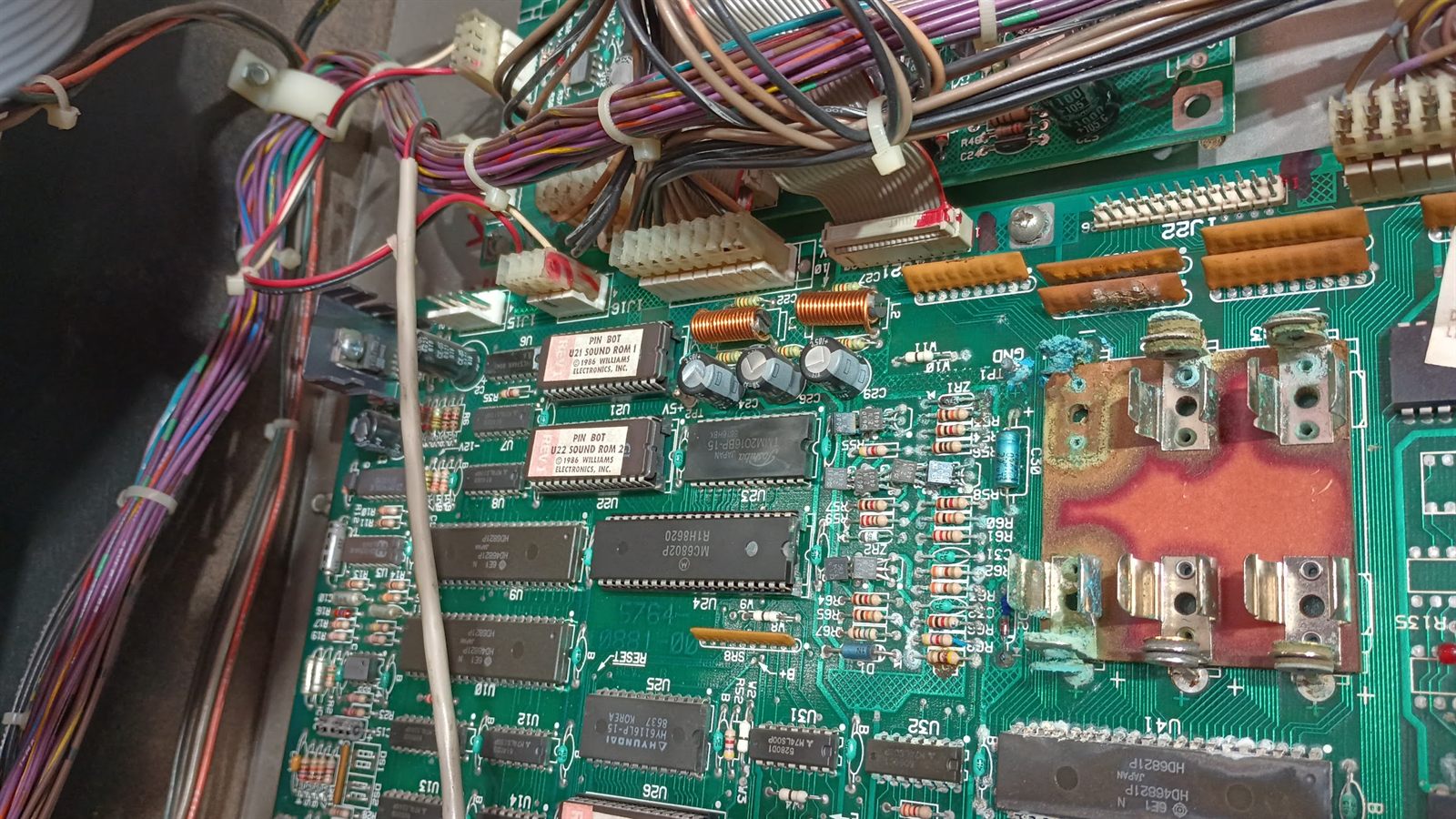
System 11 boards carry three AA cells in a holder soldered directly to the CPU board. They keep the game's settings and audits alive when the machine is unplugged, which is a perfectly sensible design and a genuinely terrible place to put batteries. Alkaline cells leak as they age. The electrolyte that comes out is corrosive, it wicks along copper traces under the solder mask, and it keeps working for years after the cells are long dead.
What makes it lethal to a board rather than merely ugly is that the damage is mostly invisible and entirely progressive. By the time a trace goes open the corrosion has usually travelled well past the holder, under components, into via barrels and up IC legs. A board that still boots can be weeks from not booting, and the repair gets dramatically harder once it has reached the chips.
On this board it had reached the chips. The photo above is what years of it looks like: the holder contacts crusted, the mask eaten off a substantial area, and the corrosion spreading outward along the traces into the surrounding circuitry.
What the Repair Involved
- Neutralize and clean. Alkaline residue has to be stopped chemically, not just scrubbed off. Anything left behind keeps eating copper after the board goes back in the machine, and a cleaning that looks finished but isn't just moves the failure a year down the road.
- Repair the damaged traces. Every run through the affected area gets checked for continuity end to end, not judged by eye. A trace that measures open gets repaired or jumpered; the corrosion frequently opens a run somewhere that still looks intact on the surface.
- Remove the old holder and move the batteries off the board. The original on-board holder came out and was replaced with an off-board holder on a lead. This is the part that matters most for the machine's future: if the cells aren't sitting on the board, the next leak, and there will be one, lands on a wire and the cabinet floor instead of on the CPU.
- Replace the corroded chip and socket it. Corrosion had got into an IC's legs. The chip was removed, the pads cleaned up, a socket fitted, and a new chip installed. The socket is deliberate: it makes the next diagnosis a chip swap instead of a desoldering job on a forty-year-old board, and repeated desoldering is itself a way to destroy pads.
If you own a System 11, or any pinball machine of that era, and you read one thing on this page, read this one: go and look at your battery holder. Not eventually. The repair above is entirely routine while the damage is confined to the holder area, and it gets expensive, then impossible, as it spreads. Moving the batteries off the board is the single highest-value preventive job available on these machines.
The Result
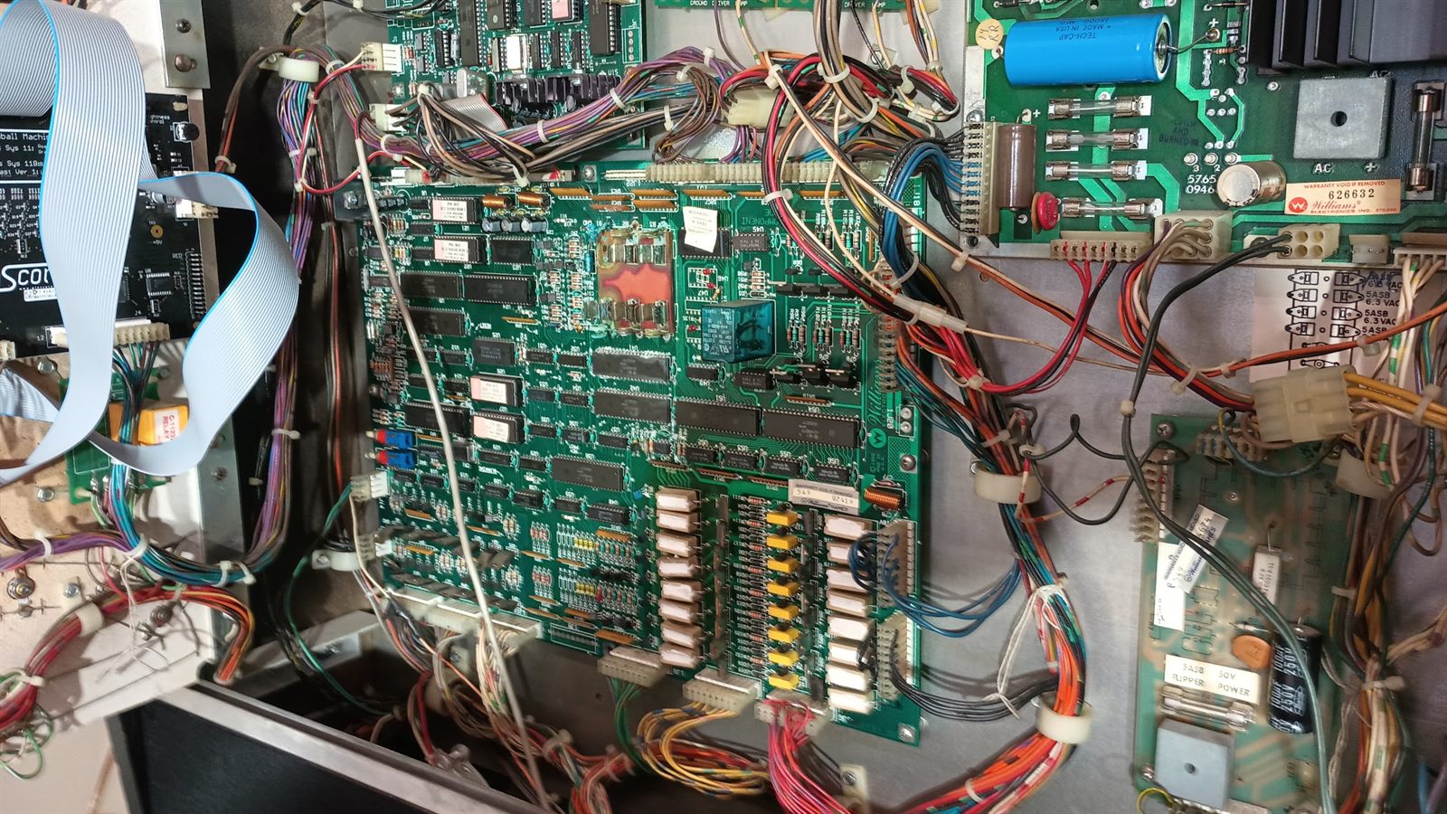
The flippers pull and hold at full strength. Switches 28 and 29 register correctly. The CPU board is clean, its damaged traces are repaired, its batteries are off the board where they can't do this again, and the chip the corrosion reached is sitting in a socket.
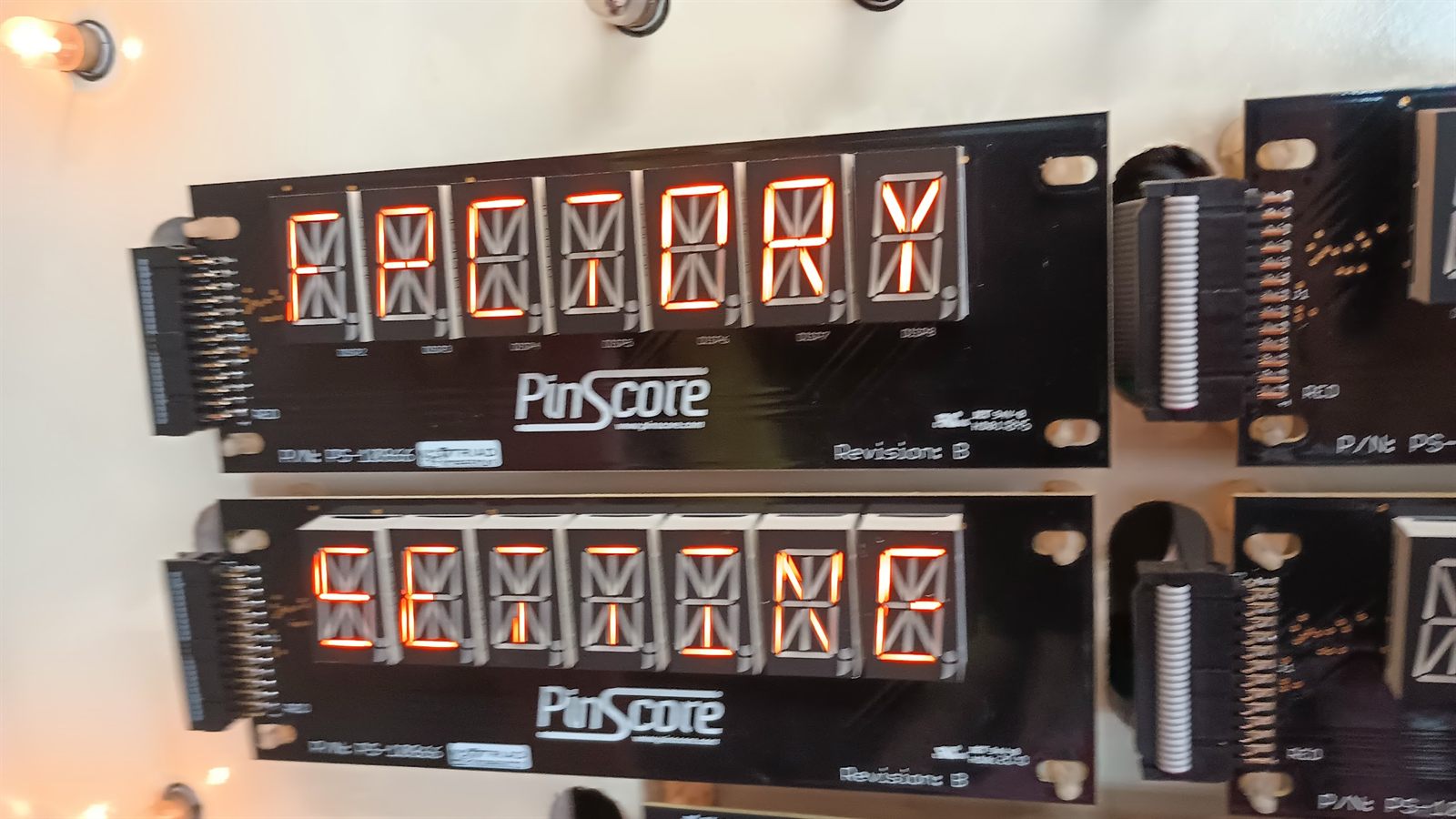
Each fault closed differently. The switches came down to two solder joints. The board came down to cleaning, trace repair and moving the batteries somewhere they can't reach it. The flipper cost the job a coil, because I wired the end-of-stroke switch wrong; that was caught before it took the harness or a driver transistor with it, corrected against the schematic, and then proved right by the machine going on working.
What This Job Shows About How We Work
When we cost a job a part, we say so and we cover it.
The second coil on this machine burned out because we wired its end-of-stroke switch wrong, and the customer wasn't charged for it. It's on the page because a repair record that leaves out the jobs where we were the cause isn't much of a record. This is how we handle it when the mistake is ours.
Stop the moment continuing costs something.
That coil came up hot and the machine went off and stayed off, instead of being run again to see whether it would repeat. A coil running away takes its connector, its harness and often a driver transistor with it. One coil is a cheap lesson. One coil plus a board repair is somebody else's bill.
Know the circuit before you trust the test.
The A-to-B jumper looked like it pointed at the coil and was actually just shorting out the power winding, away from where the problem really was. A test is only as good as the circuit model behind it, and on a parallel-wound coil the same jumper would have meant the opposite thing.
A clean bench reading is not a working circuit.
Both windings measured correct against the part number, which proved the coil was intact and said nothing about how it was connected. Resistance is blind to shorted turns, to joints that collapse under load, and to wiring. What it is good for here is identifying which lug is which by measurement, which is the thirty seconds that prevents the error this job made.
Voltage is cheap. Current is the measurement.
A meter will show near-full voltage through a connection that collapses the instant real current is asked for. The drop across each part while the circuit is working tells you something a voltage-to-ground reading cannot.
Check the explanation that covers everything first.
Two consecutive switch numbers share a column wire, so that wire got inspected before anything else. It was fine. Ruling out the single cause that would have explained both symptoms is what made two separate broken joints the credible answer instead of an unlikely coincidence.
A shared cause isn't always a shared connection.
Those two joints failed independently, on adjacent targets, from forty years of the same ball impacts and the same vibration. The wiring diagram can only show you shared conductors. The machine also has shared physics, and it doesn't document them.
Look at what nobody asked about.
Nothing in the reported symptoms mentioned the CPU board. The battery damage was found by opening the backbox and looking at it, and left alone it would have taken the machine out entirely, long after the flippers were sorted.
Let the machine confirm the repair.
A miswired flipper destroys a coil in minutes, so a coil that keeps working is direct evidence the wiring is now right, not just a hope that it is. Wherever a fault offers you a test that proves its own repair, take it. "It seems fine now" is a statement about one afternoon.
Technical Details
| Machine | Williams Pinbot, 1986, System 11 |
| Reported symptoms | Left flipper at about a quarter strength; after a coil replacement, both flippers dead in roughly ten minutes with a very hot left coil; Switch 28 and 29 reported at startup |
| Found on inspection | Extensive alkaline battery corrosion on the CPU board around the B1 to B3 holder |
| Flipper coil | FL-23-600/30-2600, 50 VDC, series wound |
| Coil measured | 2.5 Ω power winding, 75 Ω hold winding, 75 Ω end to end — correct to spec, and identifying B as the junction lug |
| Flipper fault | Original coil failed. The first replacement was destroyed by an EOS switch wired wrong by this shop, which left the coil running in a state meant to be momentary. Wiring corrected against the factory schematic; a third coil fitted. The customer was not charged for the coil we destroyed |
| EOS spec | About 0.015 in of travel before the contacts open; about 0.062 in gap when open |
| Observed under load | About 1.5 V across the power winding at roughly 0.5 to 1 A, consistent with 50 V across the full 77.5 Ω series path |
| Switches reported | 28 (Visor Target 1) and 29 (Visor Target 2), both on matrix Column 4, green-yellow at 1J8 pin 4 |
| Switch fault | Broken solder joint at each target's own row wire, both re-soldered; shared Column 4 wiring checked and intact |
| Board work | Corrosion neutralized and cleaned, damaged traces repaired, on-board battery holder removed and replaced with an off-board holder, corroded chip removed and replaced on a new socket |
| Diagnostics used | Coil resistance by winding, voltage drop across the cabinet switch and return path, direct current measurement during the stroke, Switch Edges test, continuity through the matrix row and column paths |
| Outcome | Flippers pull and hold correctly, both visor targets register, CPU board repaired with the batteries relocated off the board |
A Note on This Write-Up
This describes one machine, not a universal procedure. Flipper wiring differs between Williams generations in ways that change what a given test means, and the series-wound behavior described here does not carry over to the parallel-wound and Fliptronics machines that came later. Switch numbering, wire colors and connector pins are specific to Pinbot and should be confirmed against the manual for any other title.
Two things are labeled as method rather than as findings above: the internal defect in the original coil, which was never established because there was no reason to section it once the machine was working, and the Switch Edges procedure, which is how these get worked rather than a transcript of this particular session. The photographs on this page are of this machine and were taken during the repair; there are none of the flipper assembly or the visor targets, so nothing on this page illustrates those two faults.
If you're working on your own machine: a pinball cabinet carries line voltage and a high-voltage display supply that stays dangerous after the plug comes out, a flipper coil in a fault condition gets hot enough to burn quickly, and battery electrolyte is caustic and belongs nowhere near your eyes.
Got a Machine With More Than One Thing Wrong?
Weak coils, intermittent switches, corroded boards, burned connectors: the process on this page is the process on all of them, and it's the same one we use on computers, consoles, amps and control boards. We document what we find, explain what the measurements mean, and say plainly when something isn't settled. See pinball and arcade repair for what we cover, or what diagnosis and repair cost before you book. Route operators with machines on location should start here instead.
Prefer to describe the problem first? Send us the details →
A $20 deposit is charged when you book; it comes off what you owe for the visit and is refundable if you cancel or reschedule at least 24 hours ahead.